INTRODUCTION
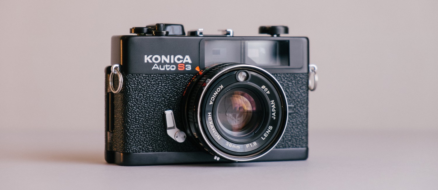
About a year ago I was awarded a generous amount of money from the Arkwright scholarship fund with which I decided to take a good old film camera and ‘digitise it’ using components taken out of the smallest digital camera I could find with a reasonably sized sensor, the Sony NEX-5. The analog camera I chose was the Konica Auto S3 rangefinder because it has a stellar fixed 38mm f1.8 lens with an unobtrusive internal leaf shutter. The viewfinder is very clear and being a rangefinder is easily adjustable for use with a different focal plane. A rangefinder mechanism allows the camera to be small (no large mirror) and won’t get in the way of the sensor which has a protruding AA filter on the front. Unfortunately the camera doesn’t have a built in diopter to adjust for glasses wearers but I managed to cut an old glasses lens of mine to fit into the viewfinder as a diopter adjustment.
PLANNING
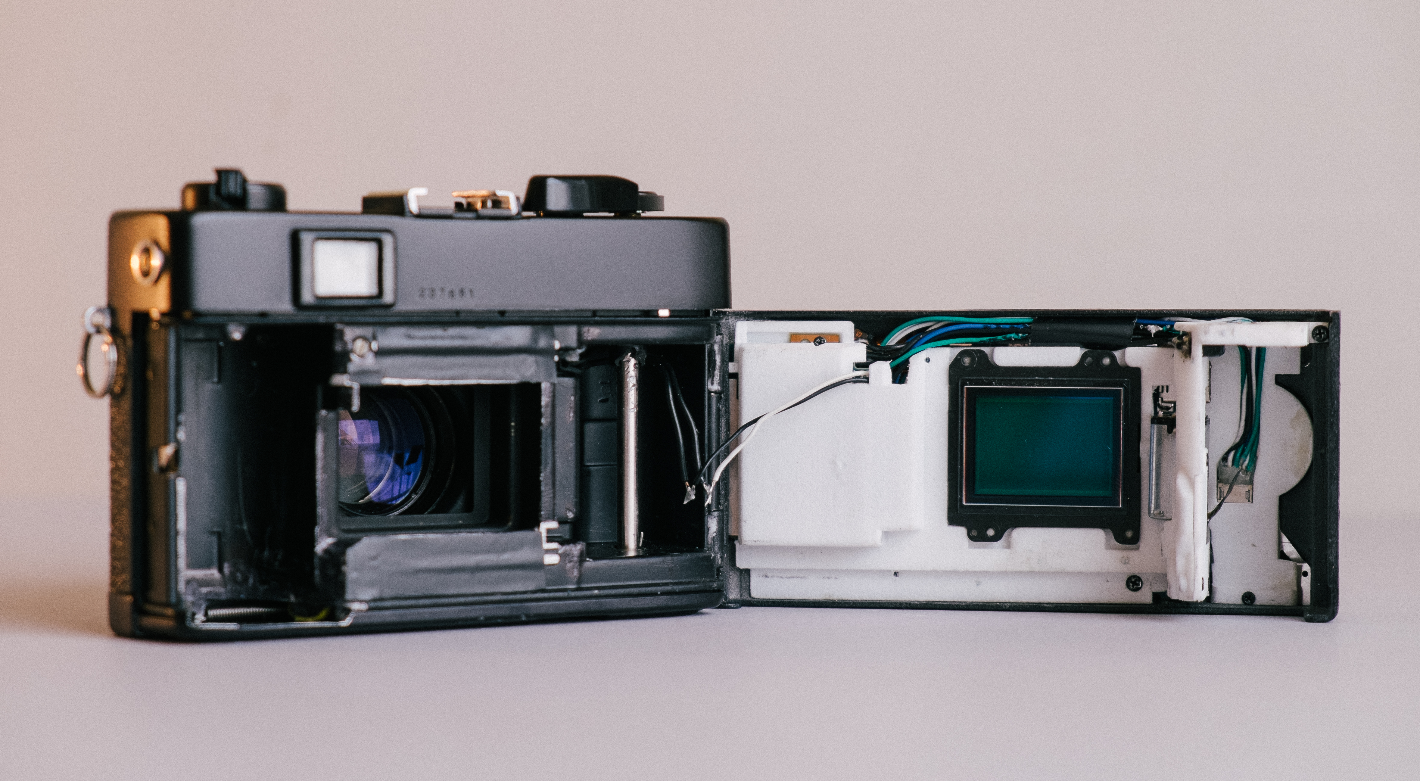
To start I dismantled a NEX-5 camera and set about trying to determine what components were necessary for the camera to function. Many of the expected components were required, the circuit board, sensor, SD card slot, battery connector. Unfortunately the camera also requires the motor module for the shutter to be attached or it shows a ‘camera error’ screen. This meant I needed to include the motor and three adjoining cogs in my already crowded design.
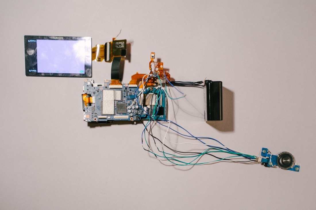
The rewired layout of the digital componenst

The cogs and motor that had to be included with cog cover attached to the motor
DESIGN
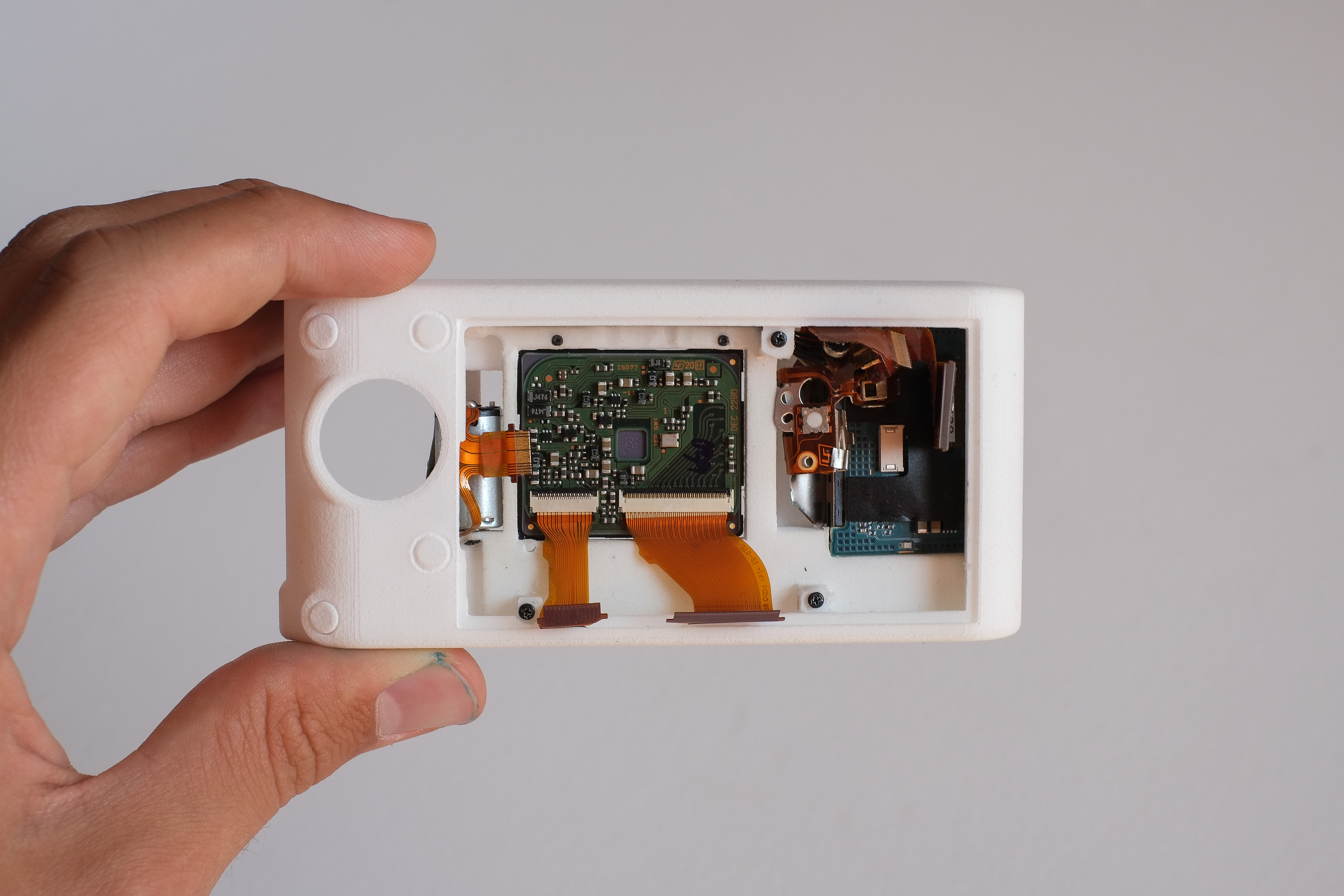
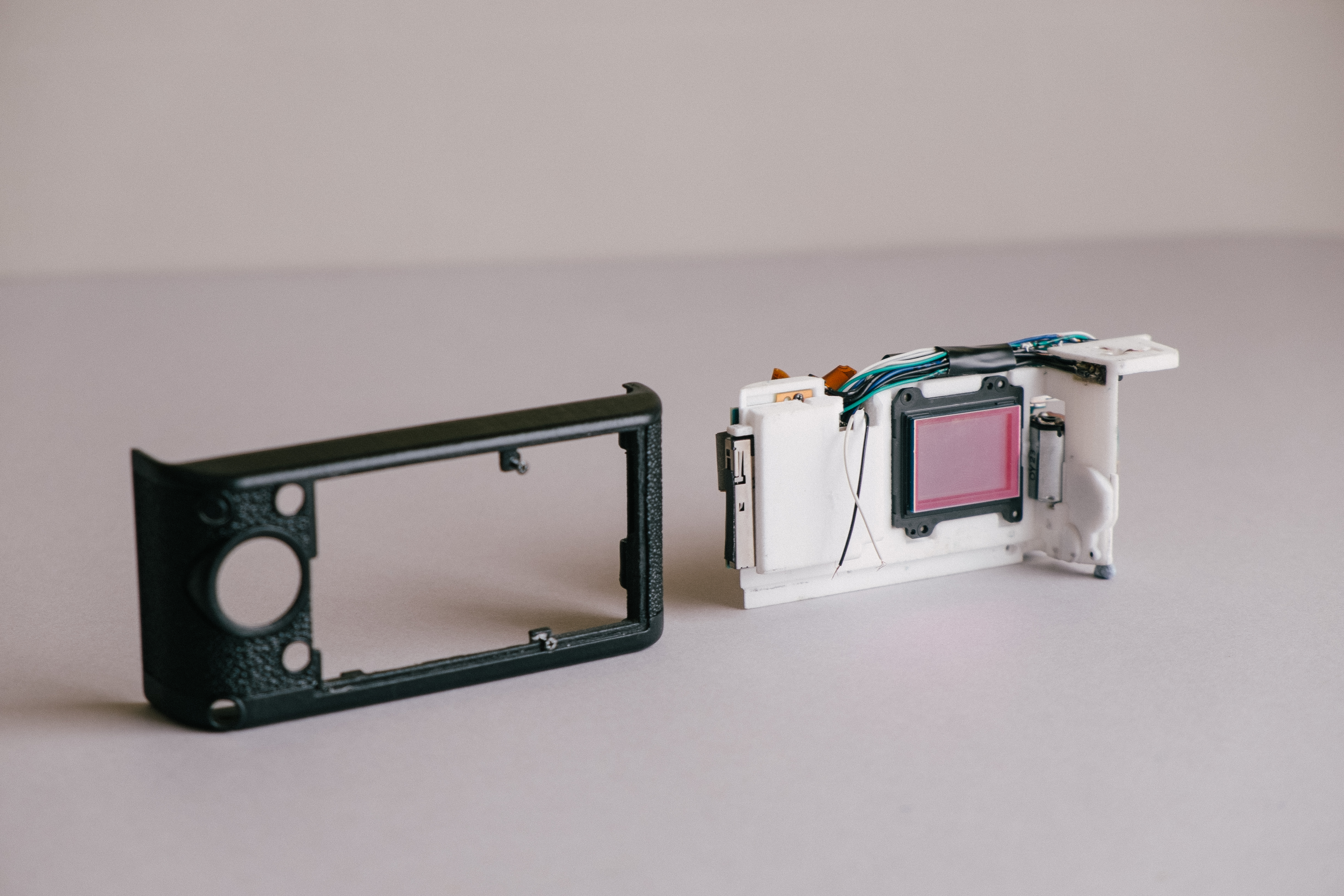
Next I needed to decide how to house the digital components and attach them to the film camera. My school had recently acquired a 3-D printer so I started designing a CAD file which would house these components using Solidworks and a pair of vernier calipers. I decided to replace the original back of the camera with a completely 3-D printed part, which is shaped to mate with the camera perfectly and to be hinged at one end with a clasp at the other to work with the original locking mechanism. I designed it in two parts, the bottom part holding the SD card slot, the sensor, the motor, cogs and battery. The top part holds the screen and buttons, and the main circuit-board is held between the two parts. In my final design there were also small covers for the cog assembly and to support the buttons.

My final CAD design shown from different angles
I also designed a replacement an ON/OFF mechanism in my final design which requires the film rewind wheel to be pushed down for the camera to turn on. This also held the design firmly in place. I also designed a replacement trigger which could house a miniature electronic switch which would be pressed as the trigger was being pressed down and released afterwards. This activates the digital sensor for the duration of the trigger being pressed (the digital camera being on the BULB setting), during which the film camera shutter is activated causing the sensor to be exposed as film would be.

The (unsoldered) replacement trigger with micro switch in place in the camera
WIRING
Most of the components could be placed roughly in their original positions and so could be connected via the original ribbon connectors but I moved the battery and the buttons to the left so the connections needed to be extended by wires. This proved difficult when soldering the wires for the buttons as there are 8 wires in a very small space and soldering onto a thin easily melted printed circuit.

Soldering the buttons
PRINTING
I first tried printing my design at school but the quality wasn’t high enough for such detailed work, so I sent my design to a 3-D printing company in London which used the incredible SLS printing method to create a strong, accurate and flexible print in nylon.

Shot of my first print
I was impressed with the quality of the first print and it was close to a final design but had some problems that couldn’t be fixed without a reprint so I redesigned it and printed it again. The result was perfect so I applied some cosmetic changes, cutting some spare leatherette to fit and painting it black. Finally I connected it to the adapted Konica, from which I removed some material to make space.

Shot of my second print


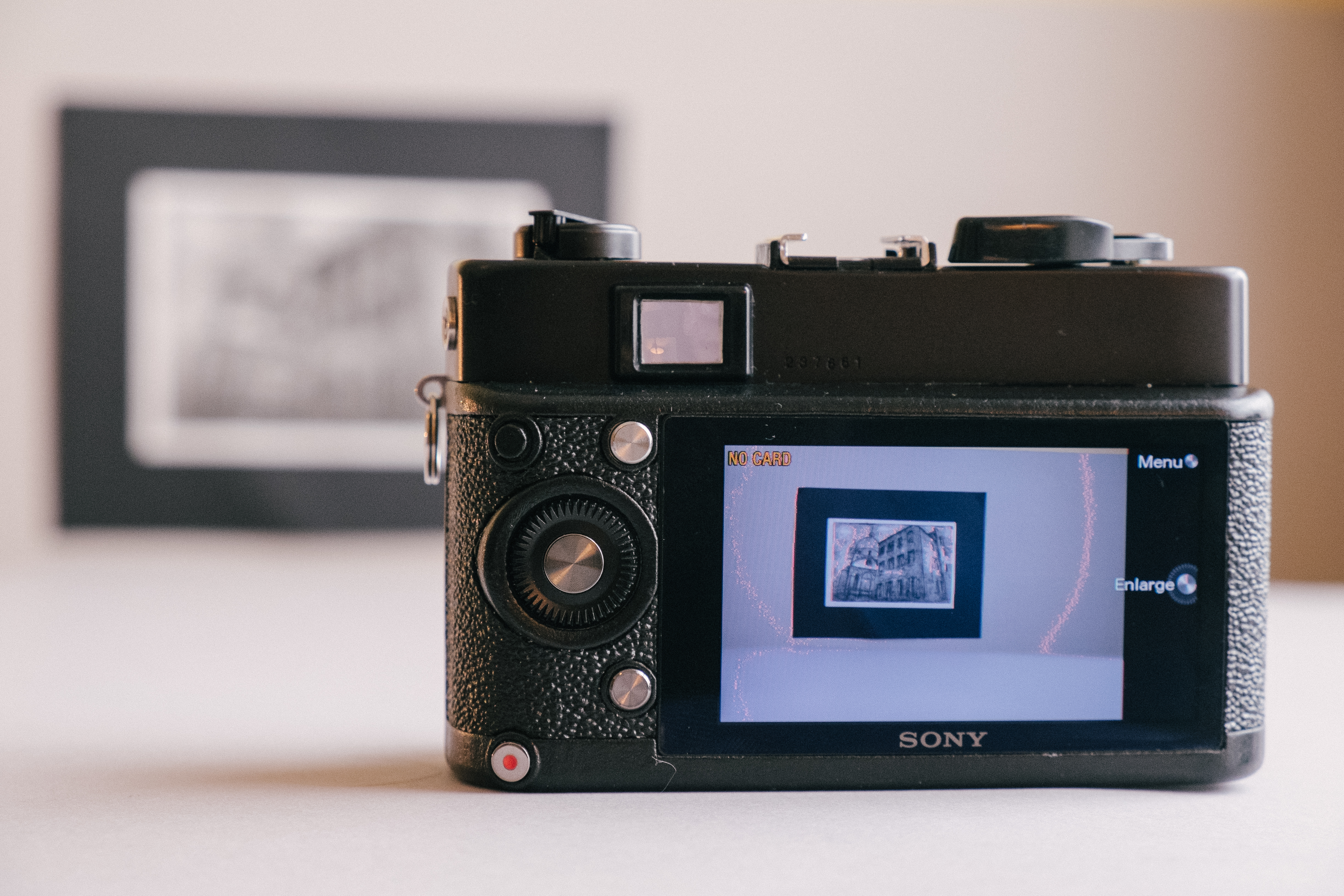
IT’S ALIVE!
After I had finished all of the assembling, I calibrated the lens to focus to infinity using the camera’s live view, and then calibrated the viewfinder to focus accurately.
VIDEOS
These videos show the operation of the camera.
EXAMPLE SHOTS

Mum – ISO 1600, f1.8

Henry – ISO 200, f4

Fascinating! Well done.
LikeLike
Nice project! I’m hoping to do something similar; taking the insides of an old 5D Mk II and building a new chassis, so this was an interesting read. Did you run into any issues on getting the flange focal distance right?
LikeLike
Thank you! I have just written an update which should answer your question
LikeLike
Congratulations!
LikeLike
Hello,
pretty good job. Congrats!
I guess you are coming from the design/Cad/3D printing side, but you should know that there a a bunch of photographers out there (me included) who would die for such a conversion.
Reason(s) for: many photogs would prefer the feeling, simplicity, and better looks of some classic film cameras. For DSLR this is not necessary because the market is flooded with good stuff. BUT for rangefinder there is only Leica who has a digital version. For some photographers the rangefinder system is the only way to go. Besides the price and limited availability, LEICA’s sensors are not up to date (imho).
I was thinking about a similar project since 1 year. Merging a classic Leica film camera or Voigtländer (etc) with the Nikon D800e interior /36 MP sensor, just for example.
By sketching it out in my mind I run into 3 major problems:
1) Nikon D800e is a modern DLSR that comes with a lot of ‘useless’ stuff which I didn’t like to take over. I also do not need the display. I could imagine that the cam then will blinking ‘Error’ when one skips some electronic parts 🙂 Same as it happens to you. Something that could not be overcome without the assistance of Nikon’s engineers 🙂 Or maybe a lot of experimenting and destroying some boards 🙂
Note: now there are some mirrorless cams on the market with the same 36 MP sensor (especially from Sony). Less parts and the merger could be a lot easier.
2) Light metering. In Nikon’s DSLR it is placed in the viewfinder, which later is no longer existent. Ok, this could probably be overcome with some experimenting and calibrating.
3) The real problems start when placing a full frame sensor closer to the lens due to vignetting and some other optical problems. Something that Leica solves with a special sensor (with microlenses). The problem is not existent (or not noteable) when a non-full frame sensor is used (like in the Epson RD digital based on a Voigtländer). But nowadays full frame is the only way to go.
Well, this is something one has to try out by building it first and checking HOW much vignetting really is there and if it could be corrected by software (on PC later).
I am not sure how good the newer full-frame mirrorless cams are on this subject. As far as I have read, it is OK but not perfect. As usual one has to check out by trying …
The body wasn’t my real problem because a close friend runs a machine shop, working in fractions of mm’s. And now there is 3D printing too. My goal was not that much to copy the classic look or case (in fact the body could look quite different), I just liked to have a cam to work with. Stripped down to the max. For now and forever! That’s why I was after the 36 MP sensor because this is all what is needed in this form factor. No need to upgrade for the next 20 years (unless a quite new technology comes out). And the cam should feature the Leica M-mount because I guess only the best Leica lenses are able to handle the demand of a 36 MP sensor. Nikon wide angles can NOT, as I have seen.
———-
Companies always have some problems by using stuff from other companies. But a private always can merge a Chevy Motor with a Ford car (or viceversa), just for example, with heading into law problems. A big advantage …
Anyway, just some thoughts because I think your project is great and so far none has commented on it. You could/should introduce it in some of the Rangefinder boards and see how the photographers respond to it. Maybe you come up with a new business idea ….
And many photogs would love to have (back) a functional rewind lever. It’s so cool 🙂
Good luck and kind regards from Austria,
Reini
LikeLiked by 2 people
Wow thank you for this great comment! I’ve posted an update which may answer some of you questions, but others I’ll try and answer here. I agree that the screen and the buttons are not good aesthetically but obviously if you get rid of the screen you dont know if things arent working so a lights system would be the perfect solution although beyond my programming ability!
The metering should not matter because you should be using the shutter and aperture on the Leica (or whatever) not the Nikon? At least thats what I did.
The vignetting should be a lens by lens trial and error thing, unfortunately could become quite expensive. There is a lot of information online about how certain Leica lenses work on digital cameras with a small flange distance, like the FF Sony a7, so that may be a good start.
Hope that helps! Not really looking for a business yet haha but thank you 🙂
LikeLike
Great project and write-up! Congrats on your success and the images look great too. If you’re too busy designing your next camera I’d be happy to beta test this one
LikeLiked by 1 person
Haha, I’ll let you know!
LikeLike
Reblogged this on stronwww.
LikeLike
Reblogged this on Scribbles and Snaps.
LikeLike
Woow, fantastic work 🙂
LikeLike
NICE! either KONY or SONICA
LikeLike
All that for what ? I bet the a6000 is a much better camera without jumping through hoops to get it.
LikeLike
Hi,
I am very impressed by your innovative approach used to convert a film RF camera to a digital RF camera. I am a member at a photography website called http://www.rangefinderforum.com. We have over 30,000 enthusiastic members who use RF cameras in addition to many other types of cameras, and there is currently a thread [http://rangefinderforum.com/forums/showthread.php?t=144458 ] in which members are discussing excitedly your report on how you converted the Konica camera. I am inviting you to join rangefinderforum and to be a member there. People are very friendly and you will not find anywhere else a more informed group of people who use RF cameras and other types of cameras. Visit our website, and see for yourself.
LikeLike
Perfect and congratulations!
You should work on a digital backs for Leicas and sell them :).
LikeLike
Well done.
LikeLike
Very interesting, good work BTW. I love the idea of the digital RF cameras. I have an Epson RD-1 and would love to own a Leica M. Looks like you might be on the right track to create a nice product. The one thing I would do in your place would be to use a FF sensor.
LikeLike
What a spectacular project! And my compliments to you for your great good taste in selecting the Konica Auto S3 as your target camera for this project.
LikeLike
You are AMAZING! (now I know what geniuses do for kicks while the rest of us are playing video games)
LikeLike
Beautiful work. As a follower of 3d printing applications and a Konica user/collector this is especially interesting. I also find it very neat that you chose the Sony innards… Sony being the inheritor or Minolta which is in turn the inheritor of Konica. Love the bokeh on that lens! 🙂
LikeLike
This is Fantastic .. I am really impressed with your engineering skills.
If you do this again, Might I Suggest an Olympus Pen film camera .
The Aps C sensor is about the same size as the negative area that Half frame camera Captures.
Also, can you send me an email ?
LikeLike
Hi Daniel,
Thank you very much! I had no idea they had half frame cameras, but thats a great idea and the camera itself looks lovely with some nice zuiko glass. At first I thought it didn’t have a viewfinder but it seems to have some crazy sideways mirror one. Do you know if the viewfinder is any good as this looks pretty interesting. Sorry I couldn’t find your email address but you can email me at frankencamera@gmail.com
Ollie
LikeLike
Sorry I’ve just looked a little more into it and the pen cameras seem to achieve half frame by taking portrait photos on half of the original 35mm size which would involve rotating the sensor, which would be impossible without a different digital camera or some horrible wiring 😦 thanks for the tip though.
LikeLike
This is really great!
My dream camera would be a Leica M3 with a digital sensor like this.
I hope you continue making cameras. An affordable [digital rangefinder][1] with only the necessary controls for photography — aperture, speed, focus and release — is needed more than ever in the photography world.
Wishing you all the best.
Simon
[1]: http://hypertexthero.com/logbook/2013/09/design-good-camera/
LikeLike
Kickstart this! I’d love to have this kind of a camera too, but don’t have the technical skills to put one together.
LikeLike
Ollie, well done mate.
I think a small fortune could be made out of these if they could be applied to wide range of film cameras.
I for one would love one.
You’re an inspiration. I am not sure if it is your youth that helped, but I’m sure most people would have given up because they’d try to make a business out of it and get caught up in all the legal matter.
I think the full frame sony sensors would also be great if they could be made to fit. I hope you do something like this again soon. Perhaps even document it so we all can do it for ourselves?
LikeLike
This is great stuff!!
Will you do one for my G2? hehe
LikeLike
Nice work, maybe you should consider moving this project to Kickstarter
LikeLike
Great ideas and great craft, salut!
But, it seems your online shop is now unavailable (This site has been temporarily disabled, please try again later). Could you get the problem fixed?
LikeLike